DCリモート入力の接続
| grandMA3 ユーザマニュアル » 最初のステップ » DCリモート入力の接続 | Version 2.2 |
grandMA3 卓、onPC command wings、および I/O Node で DCリモート入力を利用するには、光バリアセンサや押しボタンなどのメーク接点スイッチを接続します。
詳しくは Remote キーワード、リモート入出力、および DMXポートの設定 を参照してください。
|
|
ヒント |
| セッション内で最大64の入力チャンネルを使用できます。 |
|
|
ヒント |
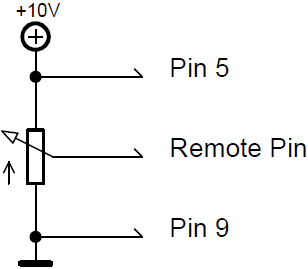
| ポテンショメータ(0〜+10V DC)を接続した grandMA3 卓や I/O Node によって、Master Fader を連続的に変化させることができます。 onPC 製品では、オン/オフは切り替えられますが、フェードはしません。 |
- アナログ入力番号1に対応する動作をさせるには、スイッチを構成するか、ピン1に外部電源から最大+ 10V DC の電圧を印加します。
- 推奨抵抗値は、5〜10kΩです。
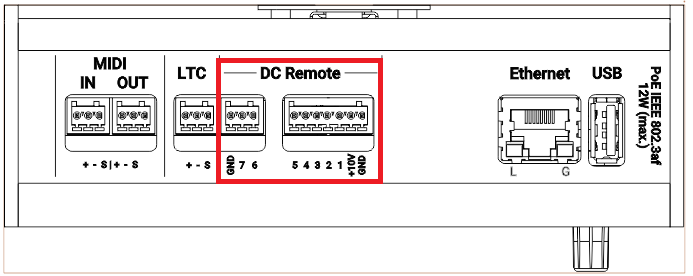
- DCリモートを利用するには、対応する入力ピンに電圧信号(最大+ 10V DC)を印加します。詳しくは後述のピン配置図を参照してください。
スイッチを構成するには、以下の2通りの方法があります。
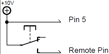
- grandMA3 卓または I/O Node のピン5からの +10V DC を利用。
― または ―
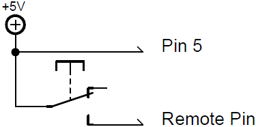
grandMA3 onPC command wing や command wing XT では +5V DC を利用。 - 外部電源(grandMA3 卓または I/O Node では +10V DC、grandMA3 onPC command wing および command wing XT では +5V DC)から供給、電源グランドは機器の共通グランドピンに接続。
+10V DC電源を、無電圧接点(スイッチ、ブザー、人感センサ、その他の接点デバイス)を介して、入力ピン1〜4または6〜8に接続してください。
回路例
- grandMA3 卓または I/O Node にポテンショメータ(0〜+10V DC)を接続
- grandMA3 卓または I/O Node でのスイッチ構成(+10V DC)
- grandMA3 onPC command wing および command wing XT でのスイッチ構成(+5V DC)
|
|
重要 |
| 卓または I/O Node のピン配置: grandMA2 卓または I/O Node には 9ピンD-sub コネクタがあり、7つのリモート入力が可能です。 ピン1 〜 4 = 入力チャンネル1、2、3、4 ピン5 = +10V DC : grandMA3 卓または I/O Node / +5V DC : grandMA3 onPC command wing および command wing XT ピン6 〜 8 = 入力チャンネル5、6、 7 ピン9 = 共通グランド |
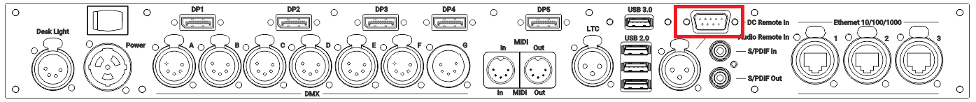
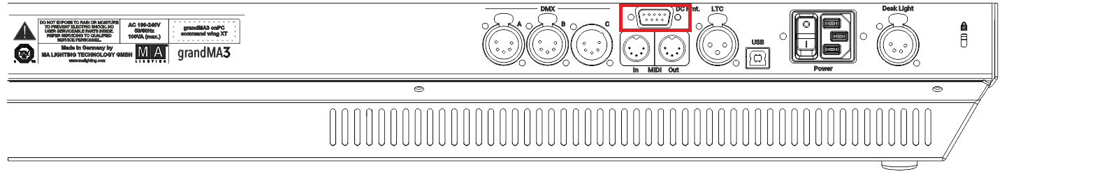
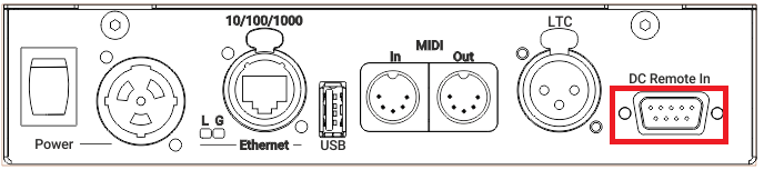
- D-sub プラグを、背面パネルの DC Remote In コネクタに接続してください。
DCリモート入力が接続されます。

D-Sub コネクタのピン配置については、コネクタのピン配置 を参照してください。