モデルのジオメトリへのリンク
| grandMA3 ユーザマニュアル » フィクスチャタイプ » フィクスチャタイプの構築 » モデルのジオメトリへのリンク | Version 2.2 |
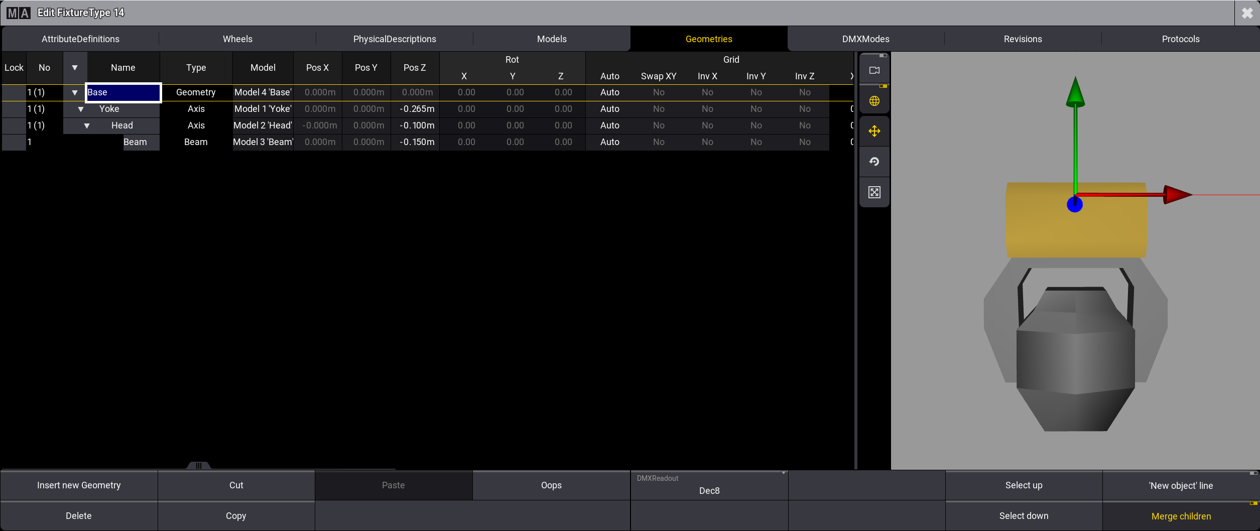
3D Viewer でモデルを正しく表示するには、次にモデルをジオメトリにリンクする必要があります。
必要条件:
- Geometries タブをタップします。
- Base モデルをジオメトリにリンクするには、Model 列のセルを長押ししてください。
- Select Model ポップアップが開きます。
- Base を選択してください。
- 個々のジオメトリで、ポジションのオフセットを設定してください。
- Base の Pos Z はデフォルト値のままにします。
- Yoke で Pos Z を -0.265m に設定します。
- Head で Pos Z を -0.100m に設定します。
- Beam で Pos Z を -0.150m に設定します。
|
|
ヒント |
| Position のオフセットは、モデルの寸法によって異なります。 |
|
|
ヒント |
| これらのセルは、Geometry Viewer で編集することもできます。 |
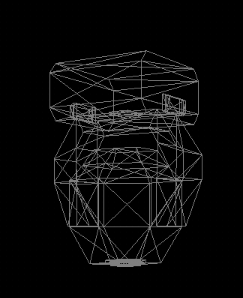
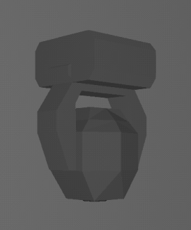
3D ウィンドウでは以下のようになります。
|
|
ヒント |
| 基本的なムービングヘッドのワイヤーフレーム表示については、3D Viewer を参照してください。 |
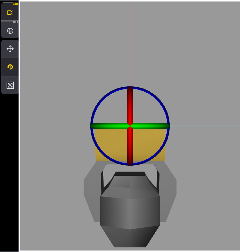
Geometry Viewer
ウィンドウの右側にある Geometry Viewer には、選択したジオメトリ・ツリーのリアルタイムな3D視覚化が表示されます。
これによって、フィクスチャのジオメトリを表示・編集できます。
|
|
ヒント |
| Geometry Viewer にジオメトリを表示するには、まず Models タブでメッシュを追加します。詳しくは モデルの挿入 を参照してください。 |
ジオメトリを編集するには、以下のようにします。
- 編集したいフィクスチャ部分をタップするか、テーブルでジオメトリを選択します。
選択された部分は、3Dエリアに黄色で表示されます。 - 色付きのインジケータのいずれかを長押しすると、ジオメトリを移動、拡大縮小、または回転できます。
対応するセルも、それに応じて変化します。
![]() (Camera
focus):
(Camera
focus):
これを有効にすると、選択したジオメトリが3Dエリアの中央に表示されます。
無効にすると、フィクスチャ全体の中心が3Dエリアの中央に固定されます。
![]() (World
model transformation):
(World
model transformation):
これを有効にすると、軸はワールドに沿って移動します。
無効にすると、軸は選択したジオメトリに沿って移動します。
![]() (Translation
mode):
(Translation
mode):
選択したジオメトリを移動します。
選択した軸の矢印をタップしたまま移動し、ジオメトリが目的の位置に移動したら指を離します。
![]() (Rotation mode):
(Rotation mode):
選択したジオメトリを回転します。
色付きのリングのいずれかをタップしたまま移動し、ジオメトリが目的の位置になったら指を離します。
ジオメトリをその軸に沿って回転させると、3D領域の左上隅に回転角度が表示されます。また、色付きの円盤には、ジオメトリの回転角度が視覚的に表示されます。
![]() (Scale
mode):
(Scale
mode):
選択したジオメトリを拡大縮小できます。
軸インジケータの1つを長押しして移動し、ジオメトリが目的のサイズになったら指を離します。
3つの軸すべてを同時にスケールするには、軸インジケータの中央にあるブロックをタップして移動します。
|
|
ヒント |
| ジオメトリを拡大縮小すると、Models タブで長さ、幅、高さの値が変更されます。 |
|
|
ヒント |
| モデルが他のジオメトリにもリンクされているジオメトリを拡大縮小すると、それらのジオメトリもスケールされます。 |
基本的なムービングヘッドを構築する最後のステップは、DMXモードとチャンネルを挿入し、それらを特定のジオメトリにリンクすることです(DMXモードおよびDMXチャンネルの挿入)。
これは、フィクスチャタイプを完全かつ正確に管理するために重要です。