Phaser Editor
| grandMA3 ユーザマニュアル » フェイザー » Phaser Editor | Version 2.2 |
Phaser Editor は、フェイザーを操作するための多様なツールです。
実行中のフェイザーを視覚化する複数の手段や、フェイザーを動的に作成・編集するためのツールが備わっています。また、フィクスチャの Position アトリビュートを調整するための簡単なトラックパッドとしても利用できます。
Phaser Editor ウィンドウは、Add Window ポップアップで開きます(ウィンドウの追加 を参照)。また、エンコーダバー の Phaser ボタンをタップすると、一時的な Phaser Editor が開きます。
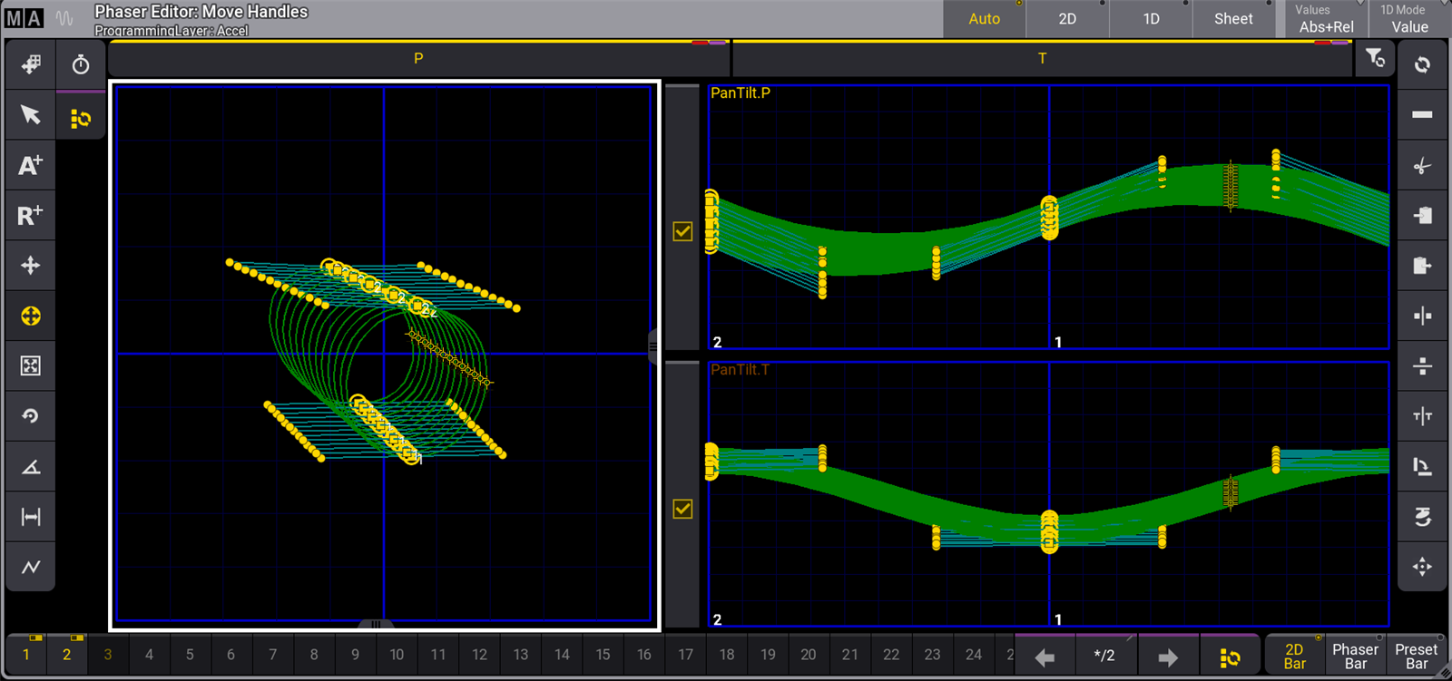
これは、Auto 表示モードの Phaser Editor の画面例です。表示モードは、タイトルバーのラジオボタンか、Window Settings ポップアップの View Mode ボタンで選択できます。利用可能な他の表示モードについては、後述を参照してください。
左側にある青いグリッドは、Pan 範囲全体(水平方向)と Tilt 範囲全体(垂直方向)を表していて、2Dレイアウトと呼ばれます。
右側の青いグリッドは1Dレイアウトです。フェイザーで複数のステップを持つアトリビュートが、それぞれに固有の1Dレイアウトで表示されます。1Dレイアウトの垂直の太い青ラインは、フェイザーのスピードに基づくビートを表しています。上の画面例では、2ステップの Pan と Tilt アトリビュートが表示されています。
フィクスチャを選択すると、小さな黄色の十字線によってそれらが視覚化されます。Window Settings ポップアップで Show Beams ボタンを切り替えると、ビームを2Dレイアウトで表すことができます。これが有効な場合、各フィクスチャのインテンシティと色が、対応する黄色の十字線の背後に大きな円として視覚化されます。
2Dレイアウトでポイントを追加すると、プログラマにステップが追加されます。最初のポイントは、指定された位置にフィクスチャをさせます。後続の各ポイントは、プログラマに別のステップを追加します。
ステップに Absolute ポイント(黄色またはシアンで塗りつぶされた四角)と Relative ポイント(黄色またはシアンの塗りつぶしなしの四角)の両方が含まれている場合、Relative ポイントと関連する Absolute ポイントが細い赤ラインで結ばれます。シアンのポイントは、その値がプリセットからのものであることを示しています。黄色のポイントは、プログラマからのハード値です。
選択されているポイントの周りには黄色い円が表示されます。
フィクスチャのパスは、緑のラインで表示されます。
タイトルバーのすぐ下のバーには、アクティブなフェイザーに含まれるアトリビュートごとにボタンが表示されます。これらのボタンは、AT Filter への直接リンクとして機能します。フェイザーの調整は、黄色のバーとテキストで表示されるすべてのアトリビュートに適用され、灰色のバーとテキストのアトリビュートについては無視されます。このバーの右端にあるボタンは、バーにあるすべてのアトリビュートの有効/無効を切り替えます。
|
|
ヒント |
| バーの一部またはすべてのアトリビュートが無効になっている場合、右端のボタンをタップすると、表示されているすべてのアトリビュートが有効になります。また、表示されているすべてのアトリビュートが有効になっている場合は、すべてが無効になります。 |
左側にあるツールボタンはマウスまたはタッチ用のツール、右側にあるツールボタンは操作機能とショートカットです(後述を参照)。左側で選択されているツールによって、右側の内容は変化します。
Step Bar
Step Bar は、Phaser Editor の下部に表示されます。これは、ステップを素早く選択するためのツールです。Phaser Editor ウィンドウでの表示はオプションで、デフォルトでは有効になっています。Window Settings ポップアップの Step Bar で表示/非表示を切り替えられます。Step Bar は、Add Window ポップアップ - More タブでウィンドウとして開くこともできます(ウィンドウの追加 を参照)。

バーには各ステップに対応する小さなマスがあります。それらは、空だったり、選択状態を切り替えたりできます。
空のステップは値を持っておらず、暗い背景色になっています。
選択されていないステップは、値は含まれていますが、ステップ固有の変化による影響を受けません。背景は明灰色で、右上隅にオン/オフ切り替えのアイコンがあります。
選択されているステップには値が含まれていて、ステップ固有の変化による影響を受けます。文字色は黄色で、右上隅のオン/オフ切り替えアイコンも黄色になります。
ステップをタップすると、選択状態が切り替わります。
バーの右側には、いくつかのコントロールがあります。ここには、ステップを1つずつ変更するための左/右矢印があります。矢印の間にある情報領域には、選択されているステップ数/空でないステップ数が表示されます。複数のステップが選択されている場合、最初のステップの後に2つのドットを付けて表示されます(例: 1.../3)。すべてのステップが選択されている場合は、最初の数字がアスタリスクになります(例: */3)。
バーの右端にある ![]() ボタンをタップすると、1つのステップだけが選択されている場合は、空でないすべてのステップが選択されます。また複数のステップがすでに選択されている場合は、ステップ1だけが選択されます。このボタンをタップすると、Step Toggle Executor というコマンドが実行されます。
ボタンをタップすると、1つのステップだけが選択されている場合は、空でないすべてのステップが選択されます。また複数のステップがすでに選択されている場合は、ステップ1だけが選択されます。このボタンをタップすると、Step Toggle Executor というコマンドが実行されます。
Phaser Editor ウィンドウの Step Bar には、3つのラジオボタンがあります。いずれかをタップすると、対応するエンコーダ・ツールバーが呼び出されます。Preset Bar は、すべてのレイヤとアトリビュートにアクセスできる標準のアトリビュート エンコーダ・ツールバー を開きます。2D Bar および Phaser Bar については、後述を参照してください。
|
|
制限 |
| ウィンドウとして開いた Step Bar には、エンコーダ・ツールバー用のラジオボタンがありません。 |
2D 表示モード
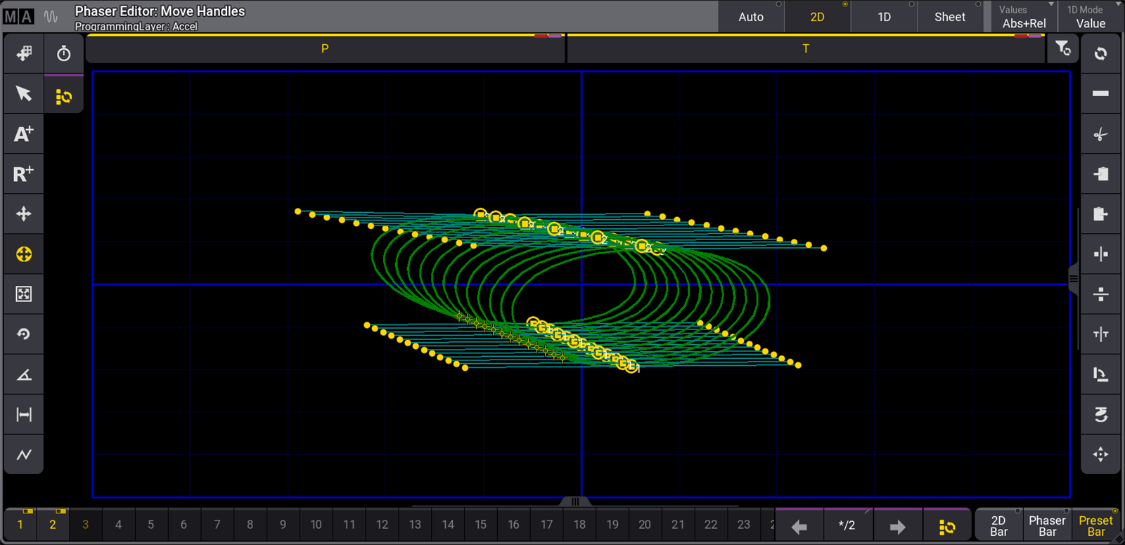
2D 表示モードでは、他のレイアウト要素が取り除かれ、2Dレイアウトがウィンドウのメイン領域を占めるように拡張されます。このモードは、Position フェイザーを操作する場合に役立ちます。
タイトルバーにある Values ボタンは、Absolute または Relative ポイントの表示や編集の許可/禁止を切り替えます。タップして順に切り替えるか、スワイプしてリストから選んでください。選択肢は以下の通りです。
- None - ハンドルだけを表示して編集できます。
- Absolute - Absolute ポイントとそのハンドルを表示して編集できます。
- Relative - Relative ポイントとそのハンドルを表示して編集できます。
- Abs+Rel - Absolute ポイントとRelative ポイント、およびそれらのハンドルを表示して編集できます。
1D 表示モード
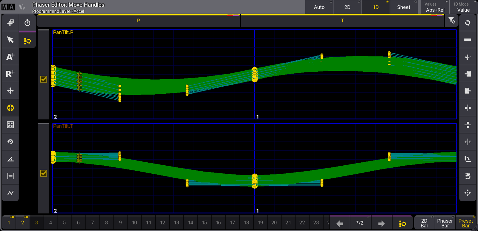
1D 表示モードでは、他のレイアウト要素が取り除かれ、1Dレイアウトがウィンドウのメイン領域を占めるように拡張されます。このモードでは、アクティブなフェイザーに含まれるすべてのアトリビュートのレイアウトが表示されます。
アトリビュート・ラインの高さを変更するには、ウィンドウ左上隅の MA をタップして Window Settings メニューを開き、LineHeight をタップして希望する高さを入力し Please を押してください。
アトリビュート・ラインの左端にあるチェックボックスは、At Filter でのアトリビュートの状態を表しています。これらのチェックボックスは、Phaser Editor の上部にあるアトリビュート・ボタンに直接関連しています。黄色のチェックマークは、対応するアトリビュートでの調整が許可されていることを示しています。またチェックを外した灰色のボックスは、調整不可を示しています。
タイトルバーの右端にある 1D Mode は、1D モードで利用可能な描画モードを切り替えます。これは、1Dレイアウトの縦軸スケールを変更します。
- Value - 各1Dレイアウトの縦軸スケールが、表示されたアトリビュートに取り得る値の全範囲に等しくなります。
- Transition - 縦軸の下端がステップの開始値を、上端が終了値を表します。
Sheet 表示モード
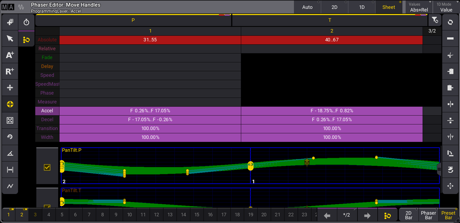
Sheet 表示モードでは、Fixture Sheet と同様のスプレッドシート形式でフェイザー・ステップを表示します。関連するすべてのスプレッドシート・データの下には、フェイザーに含まれる各アトリビュートの1Dレイアウトも表示されます。
Sheet 表示モードのデフォルト構成では、フェイザー・ステップが列として、レイヤが行として配置されます。フェイザーのすべてのステップに影響を及ぼすレイヤは、ステップ1の下にのみ表示されます。シートの各セルには、そのステップのレイヤに対するすべての値の概要が表示されます。セルに複数の値やプリセットが含まれている場合、セル内の最小値と最大値が2つのドットで区切られて表示されます。
ツール
左側には以下のツールボタンがあります。

- 1 - Move Area:
Position 範囲外の Relative 値を表示するために、青い Pan/Tilt 領域全体を移動させます。 - 2 (selected) - Select:
個々のポイントを、または投げ縄操作によって複数のポイントを選択します。タイトルバーのボタンを切り替えることで、セレクションを Absolute/Relative ステップに絞れます。 - 3 - Add Absolute:
Absolute 値でステップを追加します。エンコーダバーは Absolute レイヤになります。塗りつぶされた四角は Absolute 値を表しています。Single Step モードは、Absolute ポイントを追加している間、指やマウスカーソルがエディタ内にある限り、自動的にアクティブになります。 - 4 - Add Relative:
Relative 値でステップを追加します。エンコーダバーは Relative レイヤになります。塗りつぶしなしの四角は Relative 値を表しています。Single Step モードは、Relative ポイントを追加している間、指やマウスカーソルがエディタ内にある限り、自動的にアクティブになります。 - 5 - Move Point:
選択されているステップを移動します。Align 機能を利用することもできます。Single Step モードは、単独ポイントを移動している間、指やマウスカーソルがエディタ内にある限り、自動的にアクティブになります。 - 6 - Move Handles (現在のツールは黄色の強調表示):
選択されているステップのハンドルを移動します。Align 機能も利用できます。各ポイント/ステップには、加減速に影響を与える2つハンドルがあります。各ハンドルは、それが制御するポイントにシアンのラインで結ばれています。ポイントにタッチしてドラッグすると、両方のハンドルを一緒に動かせます。ハンドル(小さな黄色い丸)にタッチして動かすと、個別に動かせます。 - 7 - Change Size:
選択されているステップを、セレクションの中心から均等に拡大/縮小します。Align 機能も利用できます。
サイズ変更中に MA キーを押していると、選択されているすべてのステップが、セレクションの水平/垂直軸上の中心から拡大/縮小されます。 - 8 - Change Rotation:
選択されているステップを、セレクションの中心の周りで回転させます。Align 機能も利用できます。
回転中に MA キーを押していると、5°ずつの回転になります。 - 9 - Change Phase:
各フィクスチャの位相値を表す黄色いドットをオーバーレイ表示します。ここでは、選択中フィクスチャで選択されているステップから独立して、位相値をシフトできます。Atフィルタによって、個々のアトリビュートの位相を動かせます。Align および Transition モード機能も利用できます。複数のアトリビュートが異なる位相で表示されている場合、選択されているフィーチャグループが明るい色で表示されます。フィクスチャがグリッド位置に割り当てられている場合、位相値を垂直または対角方向に整列できます。これを選ぶと、右側の機能が整列のクイック選択に変わります。これによって右側のツールボタンが変化し、標準的な位相値と、Reset および Invert ボタンに素早くアクセスできるようになります。 - 10 - Change Width:
このツールで Width を変更できます。右側の機能は、種々のパーセンテージを設定するためのショートカットに変化します。すべてのステップを選択して Speed ショートカットをタップすると、各ステップ間の移動スピードが等しくなります。デフォルトでは、各ステップの Width は、ステップ内でフィクスチャが移動する距離に関係なく同じです。ステップ幅を調整して均等にすると、フィクスチャは同じスピードで移動します。Reset ショートカットは、Width をリセットします。デフォルトは100%です。これは、各ステップでのフィクスチャの移動距離に関係なく、各ステップの Width が同じになることを意味します。 - 11 - Select Form:
フォームを選択すると、Transition レイヤ、Accel レイヤ、Decel レイヤの値が上書きされ、目的のエフェクトが作成されます。利用可能なフォームは、右側のツールバーに一覧表示されます。ここには Rectangle (矩形)、Sawtooth (鋸歯状)、Sine (正弦)、および Circle があります。 - 12 - Change Speed:
タップすると、右側のツールバーにさまざまなスピード・ツールが表示されます。利用可能なツールには、現在のフェイザー・スピードを所定の数値で乗算または除算する機能が含まれています。また特別な選択肢として、以下のものがあります。- Loop: 現在のフェイザー・スピードを、現在のフェイザーにあるステップ数で乗算します。
- Fixture: 現在のフェイザー・スピードを、現在のセレクションのフィクスチャ数で除算します。
- 13 - Select all Steps:
これは他のツールとは異なります。タップすると、全ステップ選択と単独ステップの選択とが切り替わります。以前に選択されていたツールは、アクティブのままです。
|
|
ヒント |
| ツールによっては、2D および 1D レイアウトで正確に位置をタッチして調整する必要はありません。代わりに、Step Bar で目的のステップが有効になっていることを確認し、Phaser Editor の青いグリッド領域をトラックパッドとして利用して、目的の調整を行います。 |
右側には以下の標準的な操作機能があります。
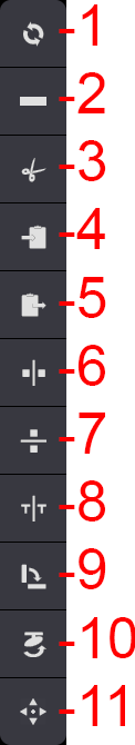
- 1 - Reset:
選択されているステップのスプラインをリセットします。 - 2 - Delete
選択されているステップを削除します。 - 3 - Cut Programmer:
現在選択されているフィクスチャのプログラマ値をすべて切り取り、それらをクリップボードに移します。 - 4 - Copy Programmer:
現在選択されているフィクスチャのプログラマ値をすべてコピーし、それらをクリップボードに移します。 - 5 - Paste Programmer:
クリップボードのすべての値を、プログラマで現在選択されているフィクスチャに挿入します。 - 6 - Mirror X:
選択されているすべてのポイントをX軸を中心に反転させます。 - 7 - Mirror Y:
選択されているすべてのポイントをY軸を中心に反転させます。 - 8 - Mirror Time:
ステップの順番を入れ替えます。最初にすべてのステップを選択しておいてください。これは、動作方向を反転させるのと同じです。 - 9 - Swap XY:
選択されているステップのX/Y軸を入れ替えます。 - 10 - Flip:
選択されているフィクスチャのポジションを反転させます。 - 11 - Reset Zoom:
青いグリッド領域をリセットします。
Phaser エンコーダ・ツールバー
Phaser Editor の右下隅にあるラジオボタン選択に応じて、エンコーダ・ツールバー は、フェイザー・データの操作に特化した便利なツールを含むものに変化します。
2D Bar
Phaser Editor の右下隅にある 2D Bar をタップすると、2D エンコーダ・ツールバーが有効になります。
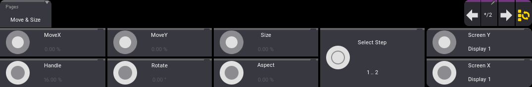
このエンコーダ・ツールバーには、以下のエンコーダ・コントロールがあります。
- MoveX: エンコーダの内側リングを回して、Step Bar で現在有効になっている全ステップの 2DPhaser グリッドにおけるX位置を調整します。
- MoveY: エンコーダの内側リングを回して、Step Bar で現在有効になっている全ステップの 2DPhaser グリッドにおけるY位置を調整します。
- Size: エンコーダの内側リングを回して、Step Bar で現在有効になっている全ステップのサイズを調整します。これによって、上述の Change Size ツールにアクセスできます。
- handle: エンコーダの外側リングを回して、Step Bar で現在有効になっている全ステップのハンドル長を調整します。これによって、上述の Move Handles ツールにアクセスできます。
- Rotate: エンコーダの外側リングを回して、Step Bar で現在有効になっている全ステップを回転させます。これによって、上述の Change Rotation にアクセスできます。
- Aspect: エンコーダの外側リングを回して、Step Bar で現在有効になっている全ステップのアスペクト比を調整します。このツールは、現在の2Dフォームの幅を広げたものや高さを増したものを作成するために、ハンドルの長さと方向だけでなく、ポイントの位置も同時に調整します。
- Select Step: エンコーダの内側または外側リングを回して、個々のステップを選択します。内側リングまたは外側リング(エンコーダ・キー)を押すと、全ステップ/単独ステップの選択が切り替わります。
Phaser Bar
Phaser Editor の右下隅にある Phaser Bar をタップすると、Phaser エンコーダ・ツールバーが有効になります。
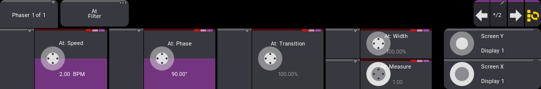
このエンコーダ・ツールバーでは、現在のフィクスチャとステップの選択、および At Filter の状態に基づいて、Speed、Phase、Transition、Width、および Measure を調整できます。
Window Settings
Window Settings ポップアップには、共通のウィンドウ設定 と Phaser Editor 固有の設定がいくつか含まれています。
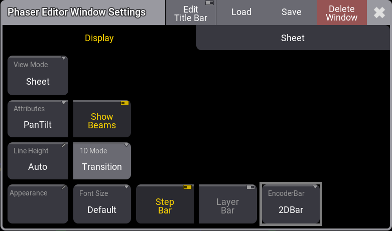
- View Mode - ビューでのさまざまなデータや情報の表示方法を指定します。これは、設定やウィンドウのタイトルバーで変更できます。
- Auto:
2Dおよび1Dレイアウトを表示します。 - 2D:
2Dレイアウトを表示します。 - 1D:
アクティブなフェイザーに含まれるすべてのアトリビュートに対する1Dレイアウトを表示します。 - Sheet:
フェイザー・ステップをスプレッドシート形式で表示し、フェイザー・アトリビュートの1Dレイアウトを表示します。
- Auto:
- Line Height - 1Dレイアウトの高さを定義します。有効なオプションの範囲は50〜500です。Auto では、この範囲内で Phaser Editor のサイズに合わせてラインが調整されます。
- Appearance - これをタップすると Select Appearance ポップアップが開き、定義されているすべてのアピアランスと、新しいアピアランスを作成するオプションが表示されます。アピアランスを選択すると、それがウィンドウに適用されます。
- Font Size - ウィンドウ内のフォントサイズを選択します。スワイプボタンをクリックすると、10〜32のサイズリストが表示されます。また、Default プロパティもあります。これは18に相当します。
- Show Beams - タップして2Dレイアウト内のビームを表示/非表示にします。
- 1D Mode - タップすると、2つの1D描画モードが切り替わります。これらのモードでは、1Dレイアウトの垂直スケールが変更されます。
- Value:
各1Dレイアウトの垂直スケールは、表示されるアトリビュートに使用可能な値の全範囲に等しくなります。 - Transition:
垂直軸の下部は各ステップの開始値を表し、上部はステップの終了値を表します。
- Value:
- Attributes - Position フェイザーを作成する際に、どのアトリビュートを使用するかを指定します。タップすると、PanTilt、XY、XZ、および YZ のいずれかに切り替わります。
- Step Bar - Step Bar の表示/非表示を切り替えます。
- Layer Bar - Layer Bar の表示/非表示を切り替えます。
- EncoderBar - Step Bar に加えて、どのエンコーダバーを表示するかを指定します。タップすると、2D Bar、Phaser Bar、および Preset Bar のいずれかに切り替わります。
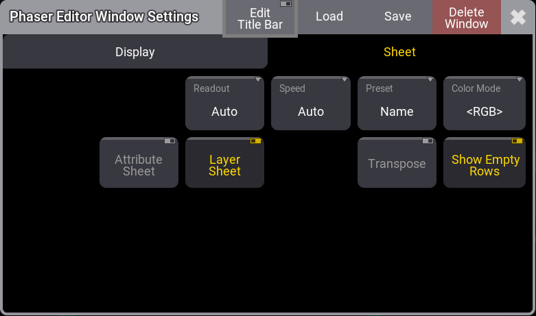
- Readout - フィクスチャ・アトリビュート値の表記法を選択します。スワイプボタンで、以下の選択肢を含むリストが表示されます。
- Auto:
シートは、エンコーダバー で選択された表記法に従います。 - Natural:
各アトリビュートには Natural な表記法が定義されています。これは Attribute Definition で定義されます。このオプションを選択すると、アトリビュートに定義されているさまざまな表記法が用いられます。 - Percent:
0〜100の範囲です。 - PercentFine:
0.00〜100.00の範囲です。 - Physical:
フィクスチャタイプ定義で指定された物理的範囲を使用します。 - Decimal8:
10進数で0〜255の範囲です。 - Decimal16:
10進数で0〜65,535の範囲です。 - Decimal24:
10進数で0〜16,777,215の範囲です。 - Hex8:
16進数で00〜FFの範囲です。 - Hex16:
16進数で0000〜FFFFの範囲です。 - Hex24:
16進数で000000〜FFFFFFの範囲です。
- Auto:
- Speed - 値の表示方法を設定します。Auto (User Profile Settings に従う)、Hertz、BPM (ビート/分)、および Seconds という選択肢があります。
- Preset - シート内でプリセット情報をどのように表示するかを指定します。以下の3つの要素を組み合わせた6つのプロパティがあります。
- ID:
プリセットのID番号を表示します。 - Name:
プリセットの名前を表示します。 - Value:
プリセットに保存されている値を表示します。
- ID:
- Color Mode - カラー表示方法を、Auto (ユーザプロファイルの設定に従う)、RGB、および CMY の間で切り替えます。デフォルト値は、User Profile Settings に従い、"<>" で囲んで表示されます。
- Attribute Sheet - フェイザーに含まれている各アトリビュートの個々の行について表示/非表示を切り替えます。Layer Sheet が有効な場合、各レイヤにはこれらの個々のレイヤがすべて含まれます。
- Layer Sheet - すべてのレイヤを同時に表示するか、アトリビュート・エンコーダで現在アクセス可能なレイヤだけを表示して他を隠すかを切り替えます。
- Transpose - ウィンドウ内の列と行を反転します。
- Show Empty Rows - 空行の表示/非表示を切り替えます。